
1 / 10

Technical Overview
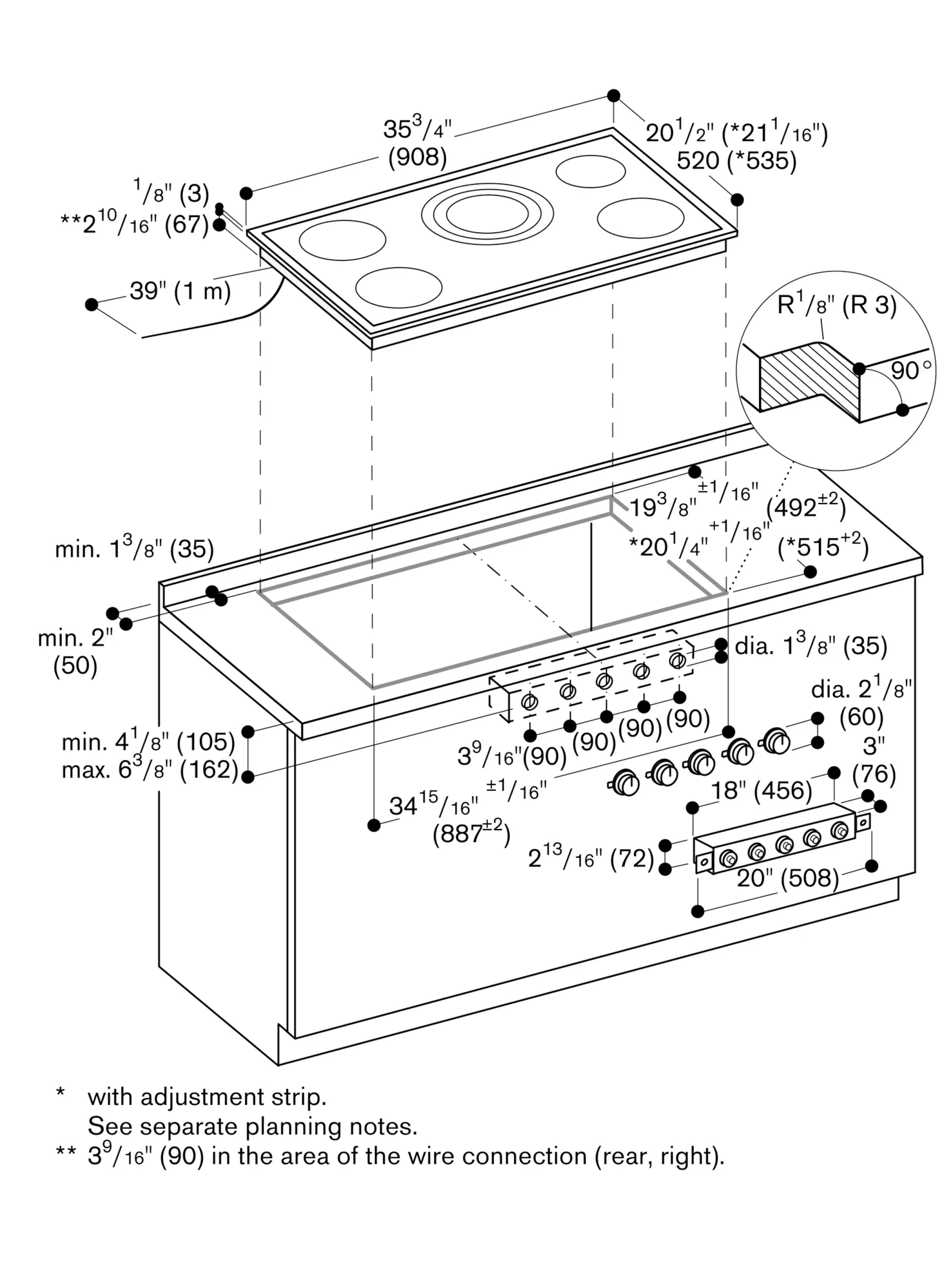
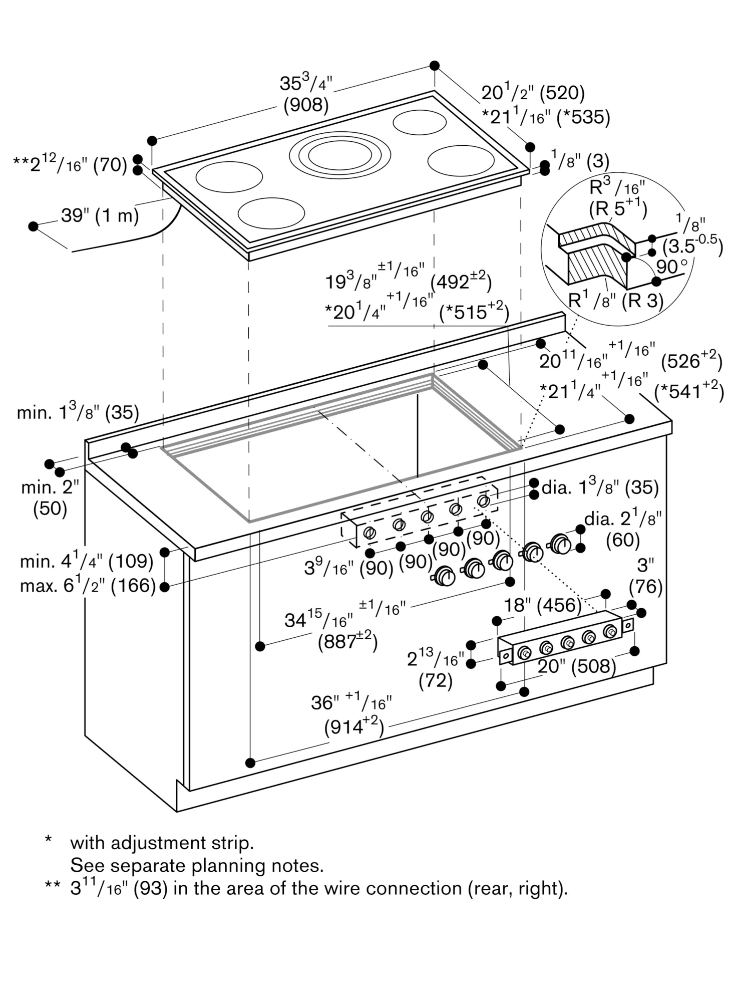
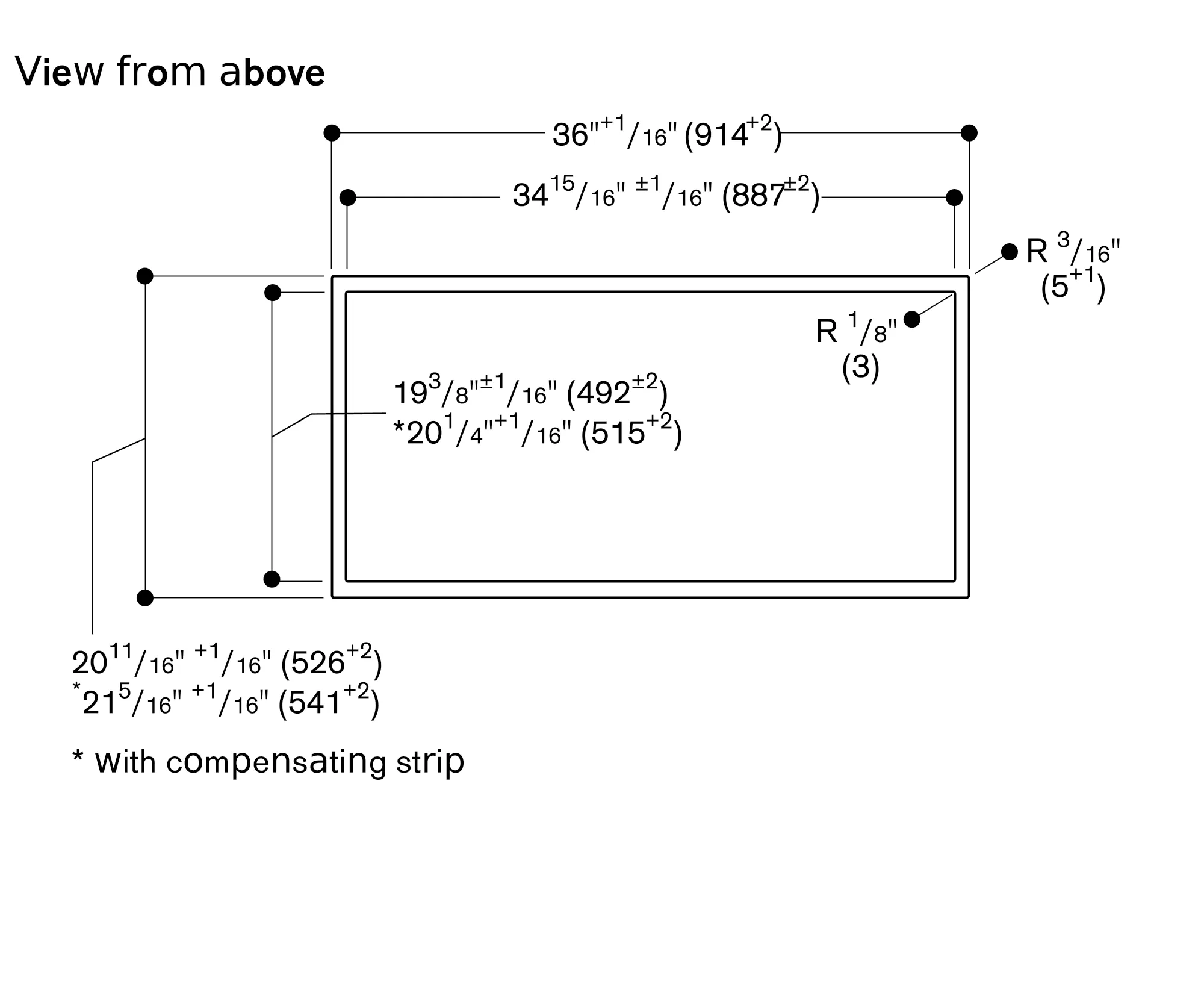
Overall Appliance Dimensions (HxWxD) (in)
1/8 + 3 3/4 x 35 3/4'' x 20 1/2''
Required Cutout Size (HxWxD) (in)
3 3/4 x 34 7/8 x 19 5/16
Additional information
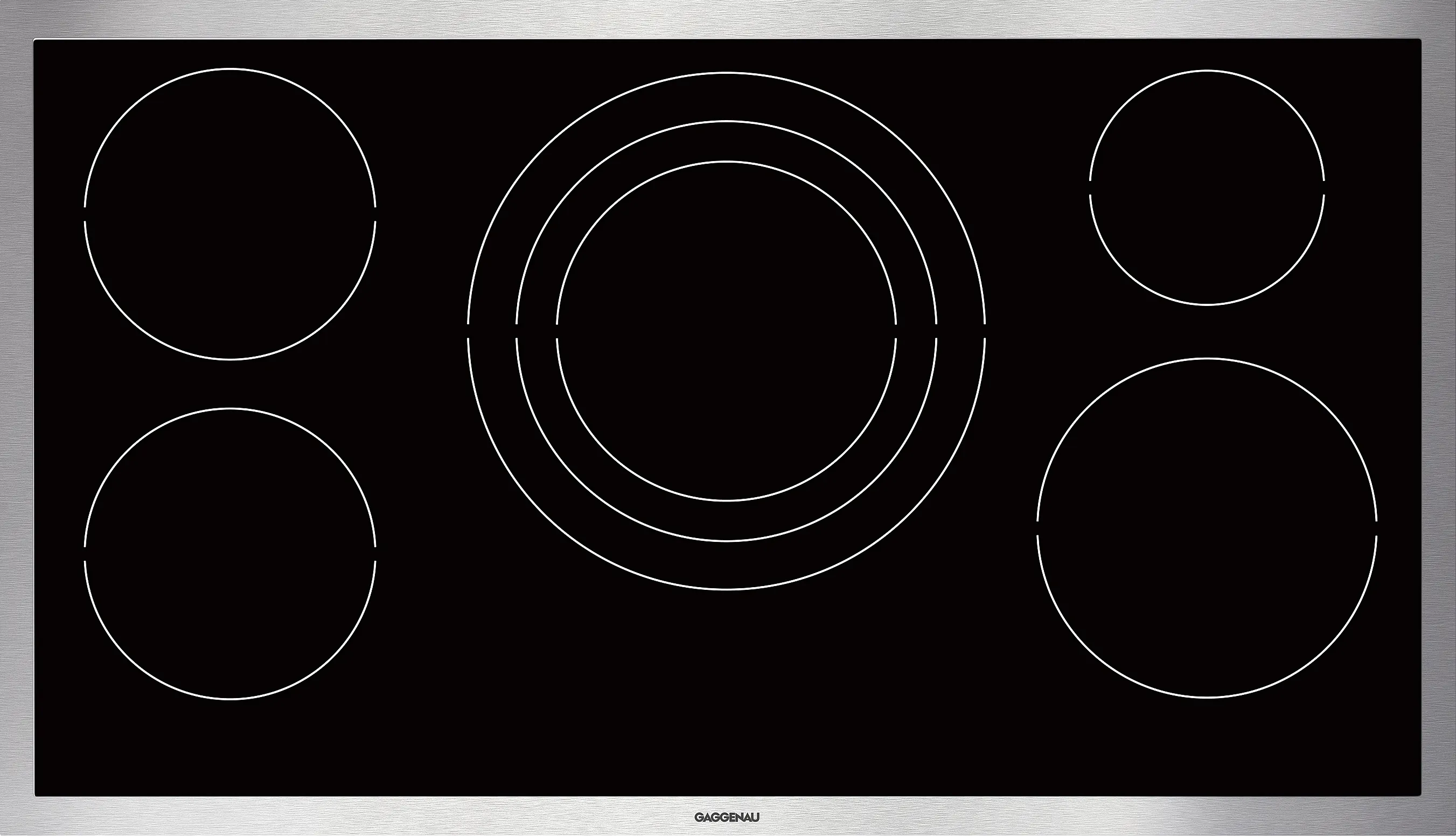
Five cooking zones with booster for cookware with a diameter of 5" to 13"
Solid stainless steel control knobs
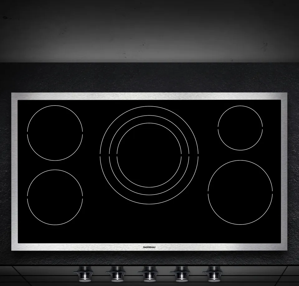
Precision crafted 1/8-inch stainless steel frame
For surface-mount installation with a visible edge or for flush installation
Can be perfectly combined with other Vario 400 series appliances
1 induction cooking zone ø 8" (2,200 W, with booster 3,300 W), automatically switches to ø 10" (2,600 W, with booster 3,400 W) and to ø 13" (3,300 W, with booster 4,600 W).
1 induction cooking zone ø 21 cm (2200 W, with booster 3300 W).
2 induction cooking zones ø 18 cm (1800 W, with booster 2500 W).
1 induction cooking zone ø 6" (1400 W, with booster 1800 W).
Control knobs with illuminated ring, cooking zone and output level markings.
Electronic control in 12 output levels.
Cooking zone marking.
Booster function for each cooking zone.
Super booster function for ø 13" cooking zone with 4.6 kW
Pot detection.
Short-term timer.
Individual residual heat indication.
Safety shut-off.
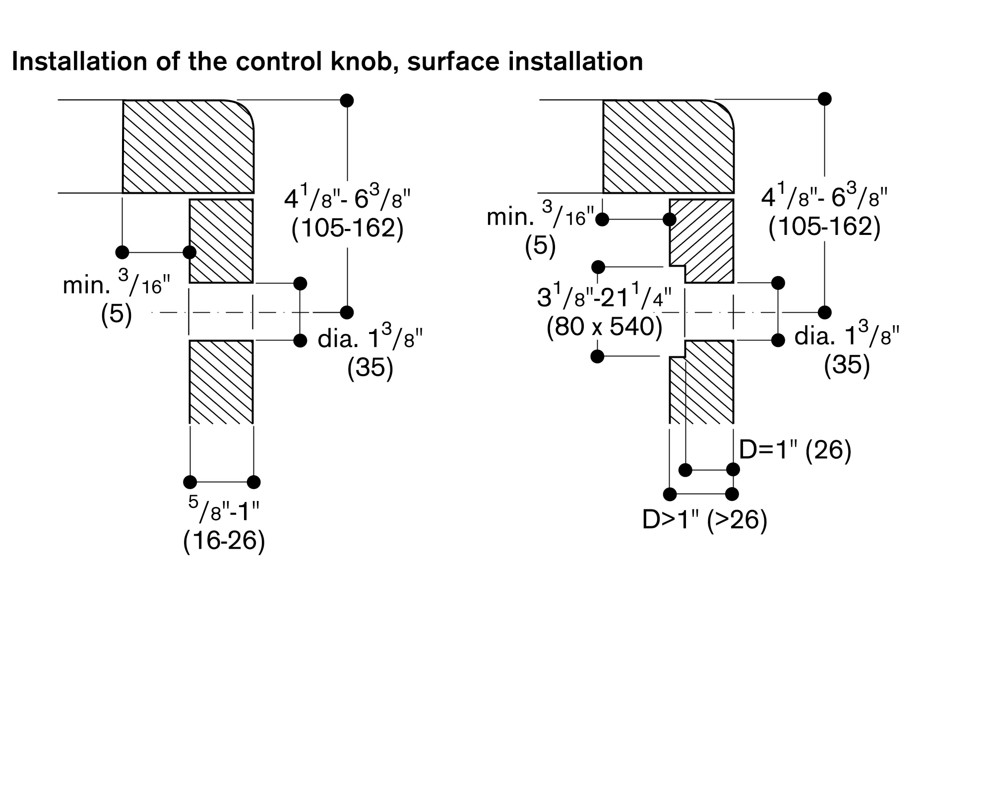
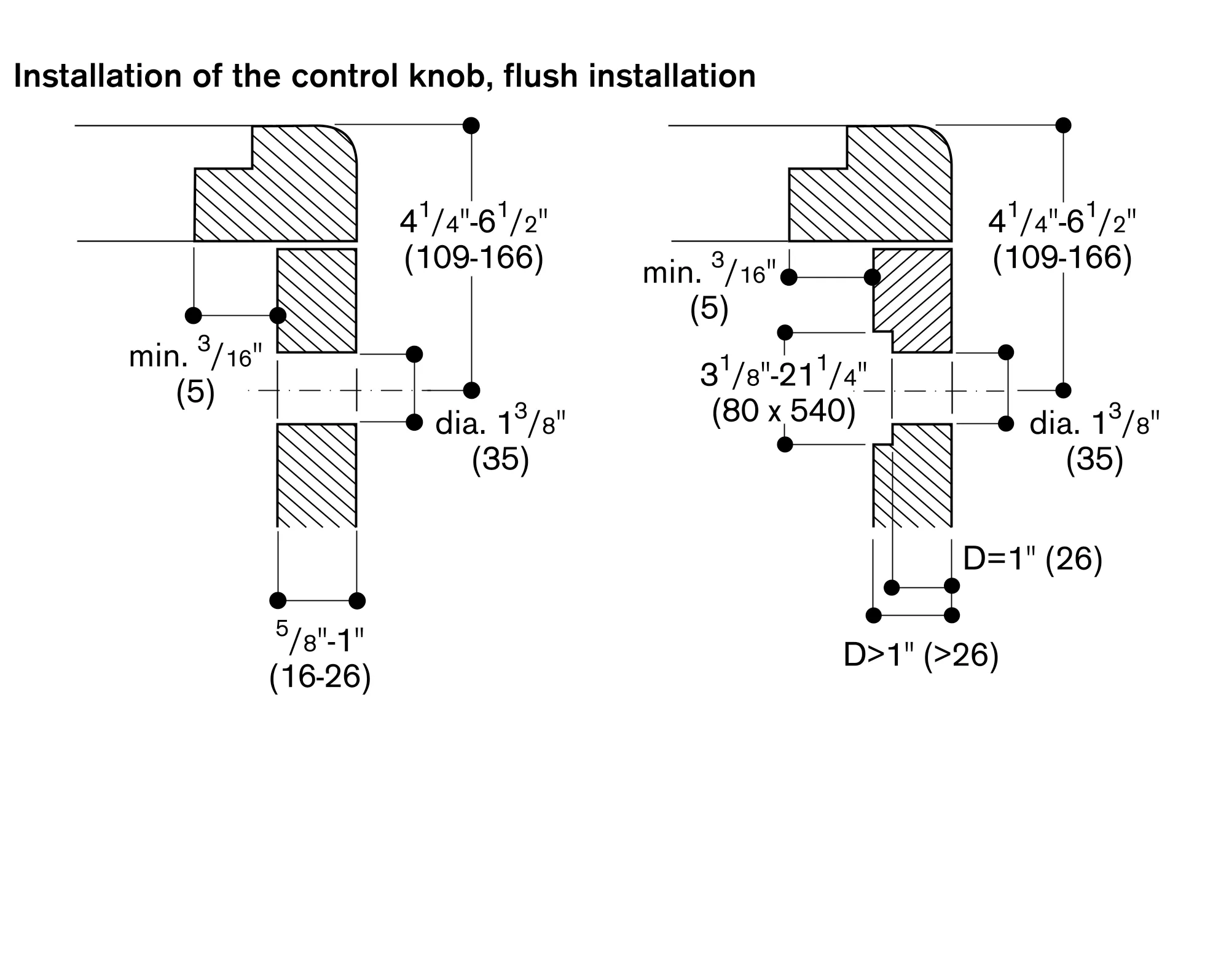
Depending on the type of installation — surface-/ or flush-mounted, with or without cover — the specific location of the control knob positions may vary.
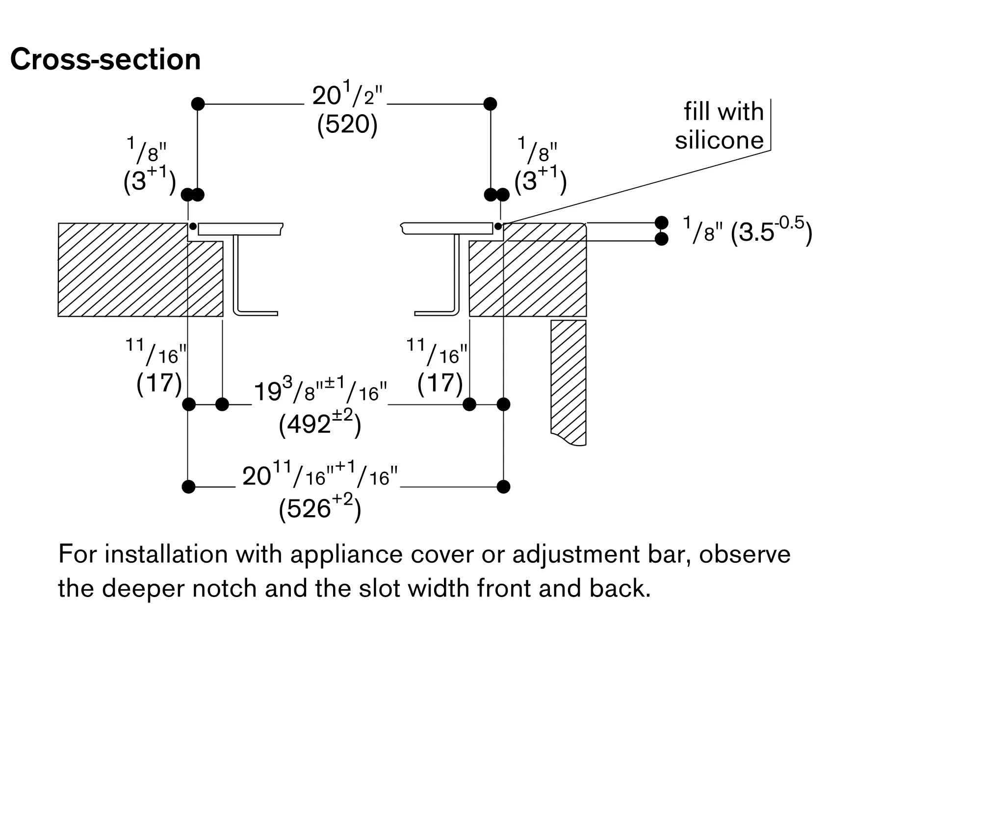
When using the appliance cover VA 440 or adjustment strip VA 450 additional space for cut-out depth needs to be considered.
If combining several appliances with at least one cover, the filler strip VA 450 is required to compensate for the depth of the appliances without the appliance cover.
If combining several Vario appliances of the 400 series, a connection strip VA 420 must be placed between the appliances. Depending on the type of installation, the corresponding connection strip must be provided.
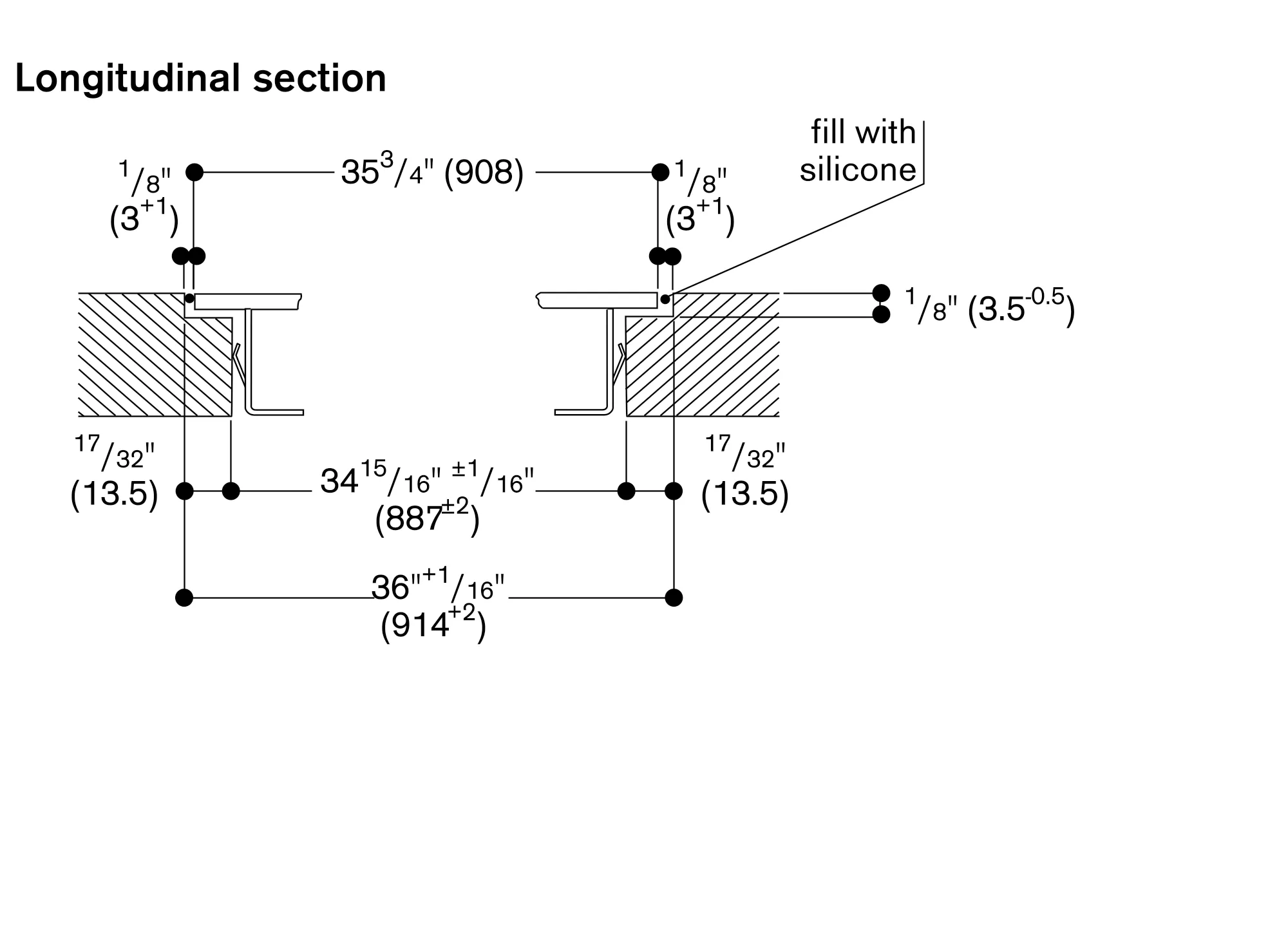
In the cut-out, the installation system requires the side edge to be at least ⅜" (10mm) for surface mounting and at least ½" (13 mm) for flush mounting. Ensure a continuous cut surface of 90°.
The bearing capacity and stability, in the case of thin countertops in particular, must be supported using suitable substructures. Take into account the appliance weight and additional loads.
Additional instructions for flush mounting:
Flush installation is possible in countertops made of stone, synthetics or solid wood. Heat resistance and watertight sealing of the edges must be observed. For other materials, please consult with your countertop manufacturer.
The groove must be continuous and even, so that uniform placing of the appliance on the gasket is ensured. Do not use discontinuous lining.
The joint width may vary due to size tolerances of the combinations and of the countertop cut-out.
If installing several appliances in individual cut-outs allow for a division bar of inimum 1 ³¹⁄₃₂" (50 mm) between the individual cut-outs.
Operates with magnetic (induction) iron pots and pans only. For an optimal heat distribution, the use of flat bottom cookware is recommended.
The wok pan WP 400 001 cannot be used with this appliance.
Immersion depth 90 mm.
Built-in control panel to be integrated in the bottom cabinet at drawer level.
Panel thickness 16 - 26 mm.
The drawing "Installation of the control knob" must be observed if the panel is more than 26 mm thick (there must be a recess at the rear).
A combination with VL 414 downdraft is not recommended due to insufficient air extraction from the center zone.
Appliance can be snapped into the worktop from above.
Appliance weight: approx. 33 lbs (21).
Total rating: 208/220 - 240 V : 10.8 kW. 60 Hz
Plan for 47 1/4" connecting cable without plug (hardwire required)