
1 / 10

Additional information
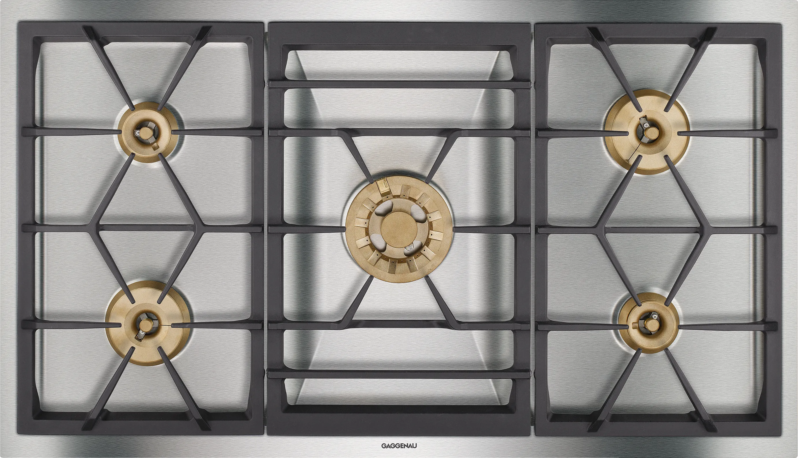
Five multi-ring burners, up to 18 kW
Automatic fast ignition, electronic flame monitoring
Solid smooth-surface cast pan supports
Solid stainless steel control knob
Precision crafting of 3 mm stainless steel
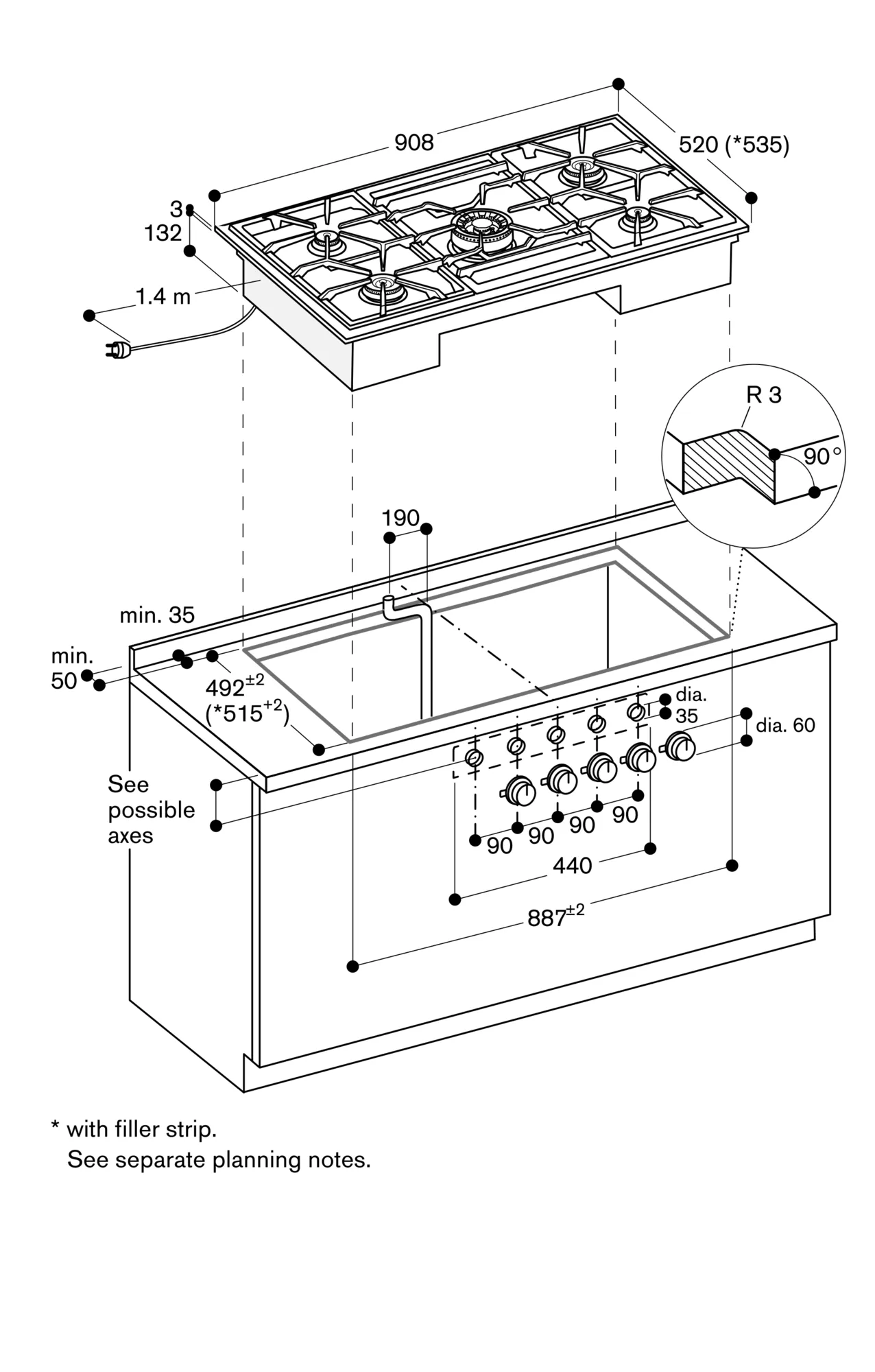
For surface installation with a visible edge or for flush installation
Can be combined perfectly with other Vario appliances of the 400 series
1 three-ring wok burner (300 W – 6000 W), suitable for pots up to max. ø 32 cm.
2 two-ring high output burners (160 W – 4000 W), suitable for pots up to max. ø 28 cm.
2 two-ring standard burners (160 W – 2000 W), suitable for pots up to max. ø 28 cm.
Control knobs with cooking zone and output level markings.
One-handed operation.
Three-part cast pan support with flat, continuous pot surface.
Brass burner rings.
Electronic flame monitoring with automatic re-ignition.
Automatic fast ignition.
Safety shut-off.
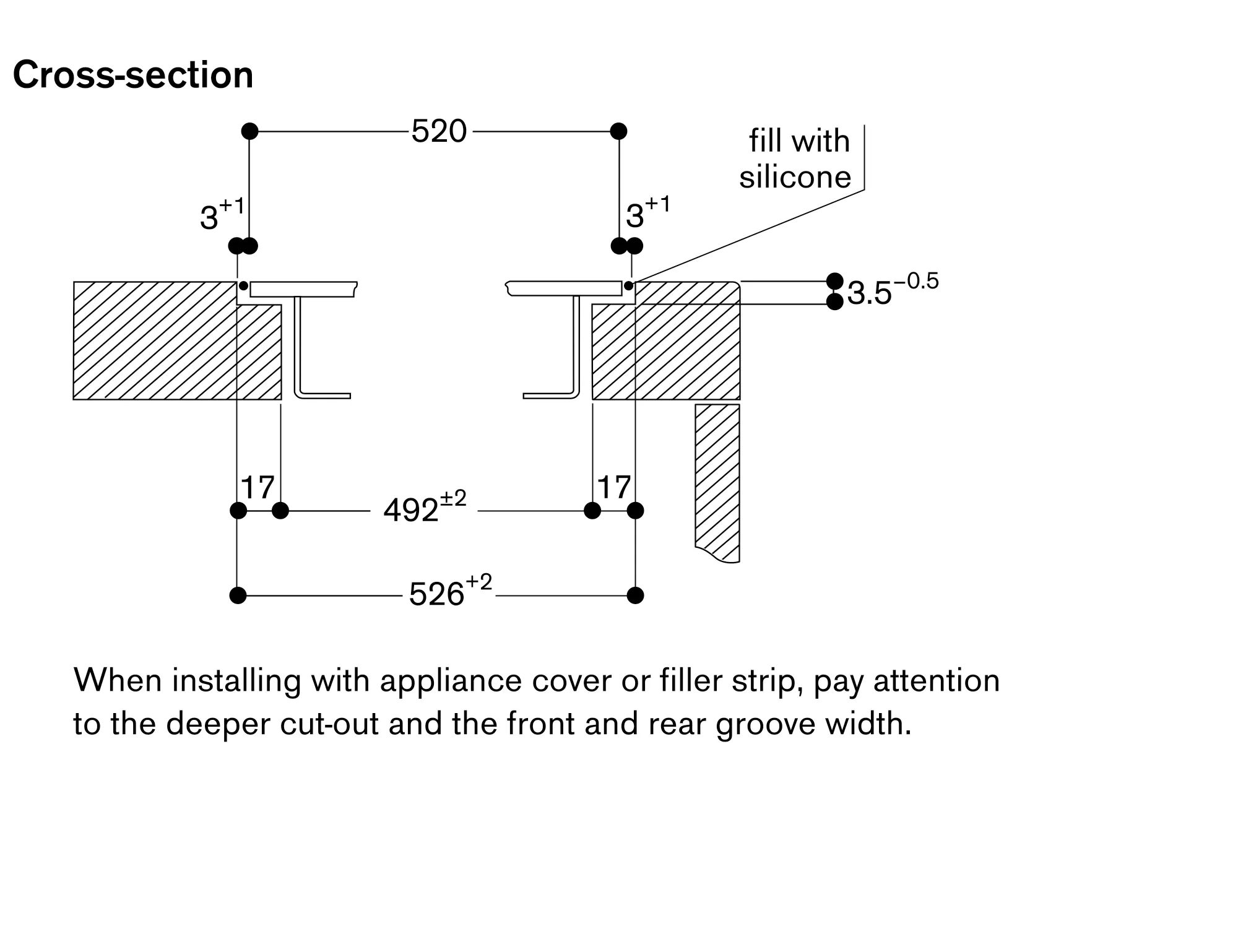
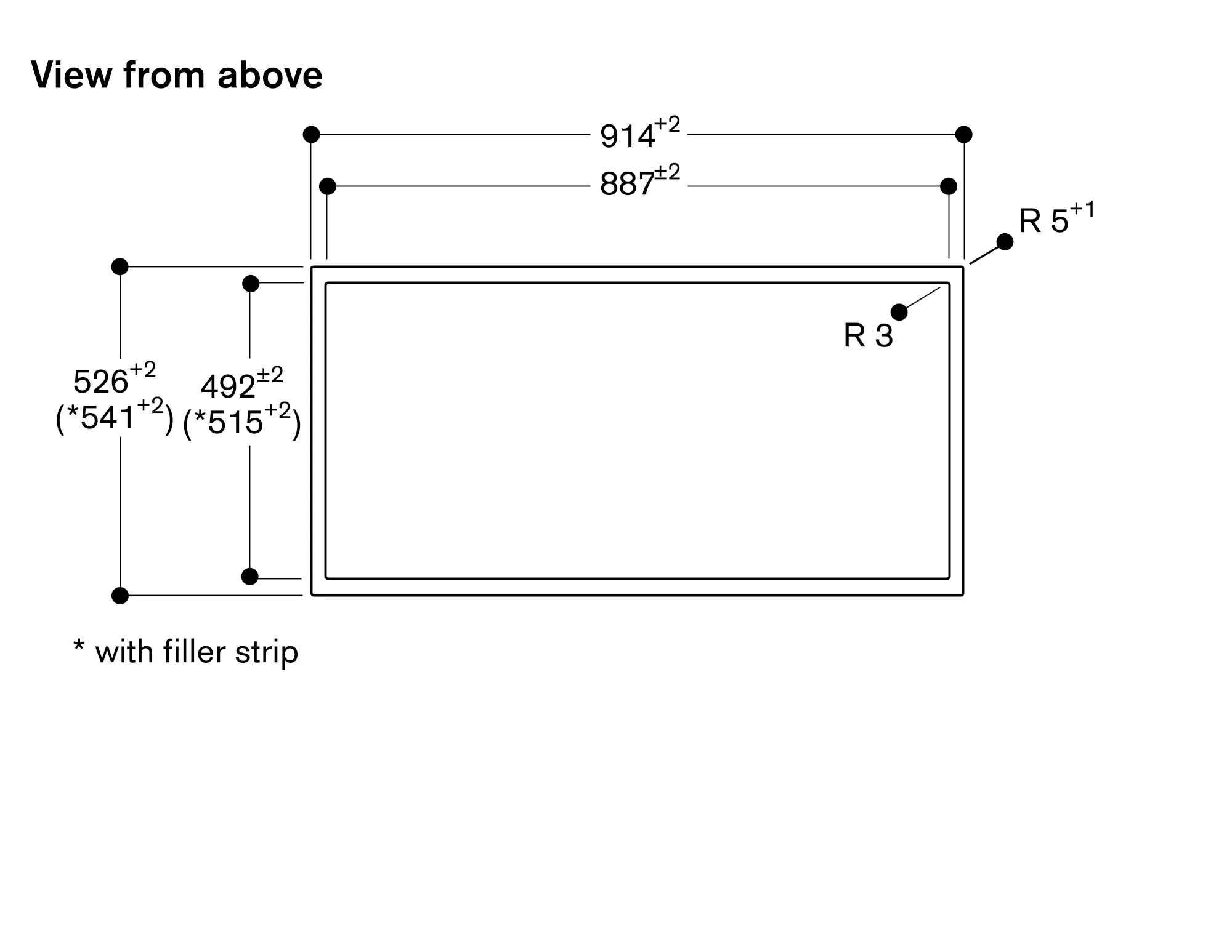
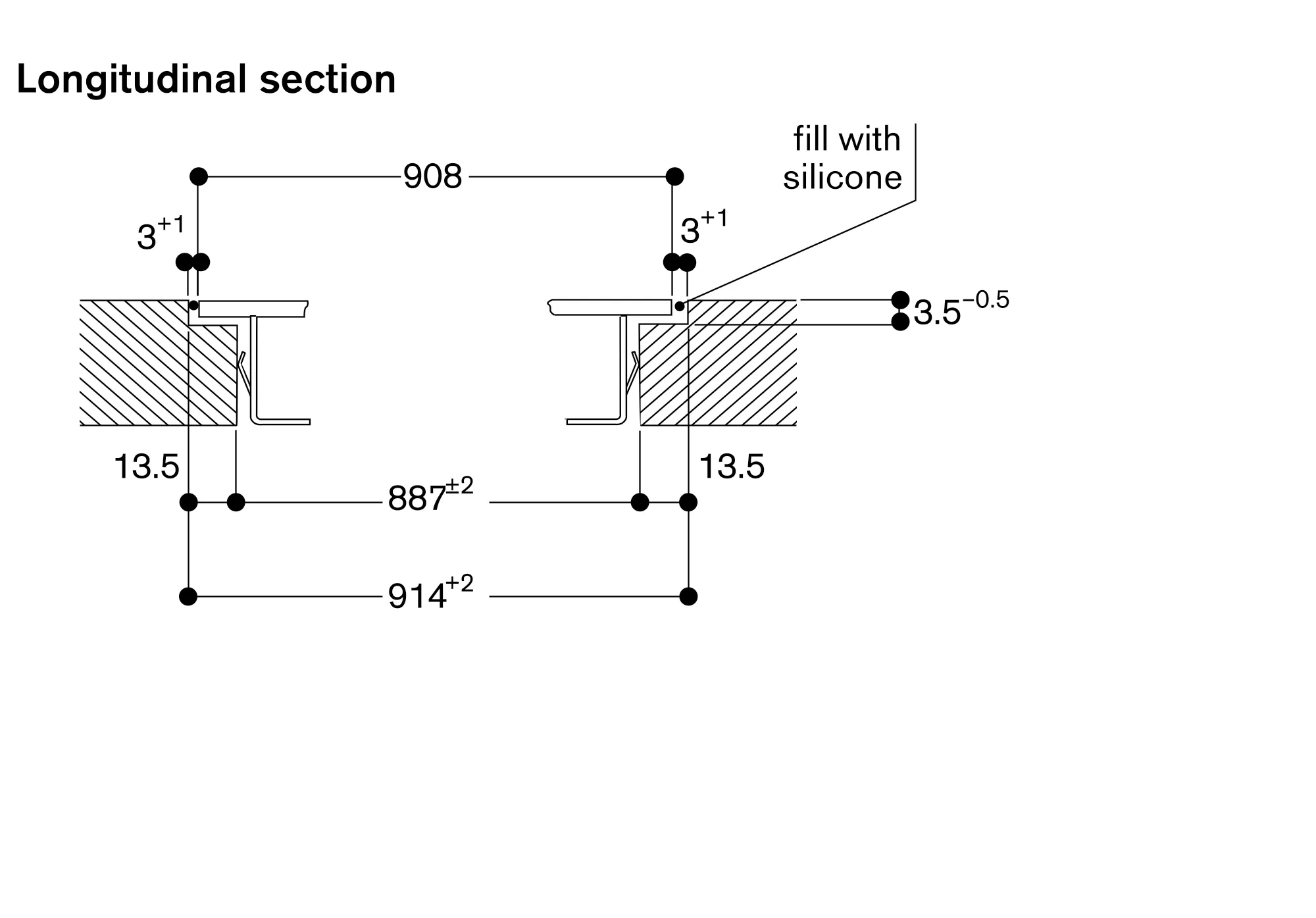
Depending on the type of installation (surface-mounted or flush-mounted, with or without an appliance cover), the specific location of the cut-out and the knob positions may vary.
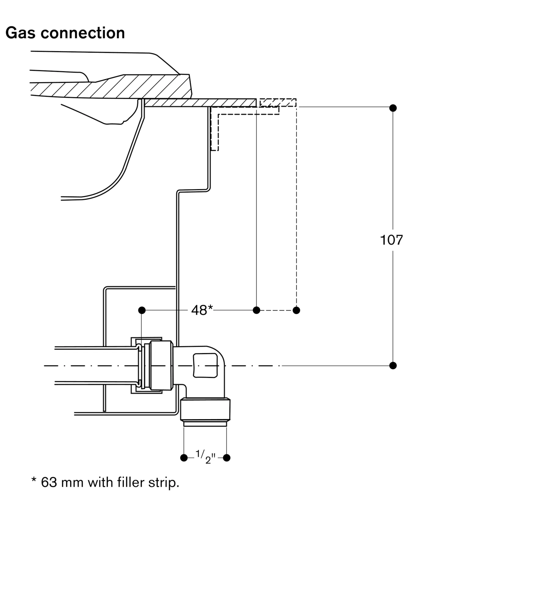
If installing with the appliance cover VA 440 or adjustement strip VA 450 take into account the additional space required for the depth.
If combining several appliances with at least one appliance cover, the adjustment strip VA 450 is required to compensate for the depth of the appliance without the appliance cover.
If combining several Vario appliances of the 400 series, a connection strip VA 420 must be placed between the appliances. Depending on the type of installation, the corresponding connection strip must be provided.
In the cut-out, the installation system requires the side edge to be at least 10 mm for surface installation and at least 13 mm for flush installation. Ensure a continuous cut surface of 90°.
The bearing capacity and stability, in the case of thin worktops in particular, must be supported using suitable substructures. Take into account the appliance weight and additional loads.
Additional instructions for flush installation:
Installation is possible in worktops made of stone, synthetics or solid wood. Heat resistance and watertight sealing of the cut edges must be observed. Concerning other materials please consult the worktop manufacturer.
The groove must be continuous and even, so that uniform placing of the appliance on the gasket is ensured. Do not use discontinuous lining.
The joint width may vary due to size tolerances of the combinations and of the worktop cut-out.
If installing several appliances in individual cut-outs allow for a division bar of minimum 50 mm between the individual cut-outs.
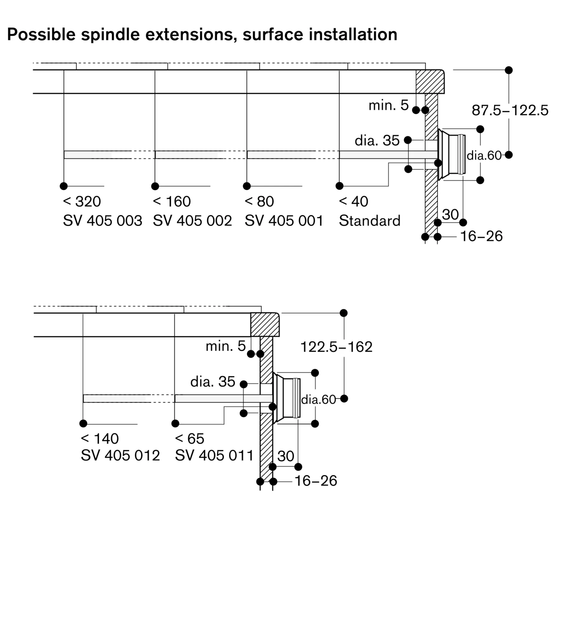
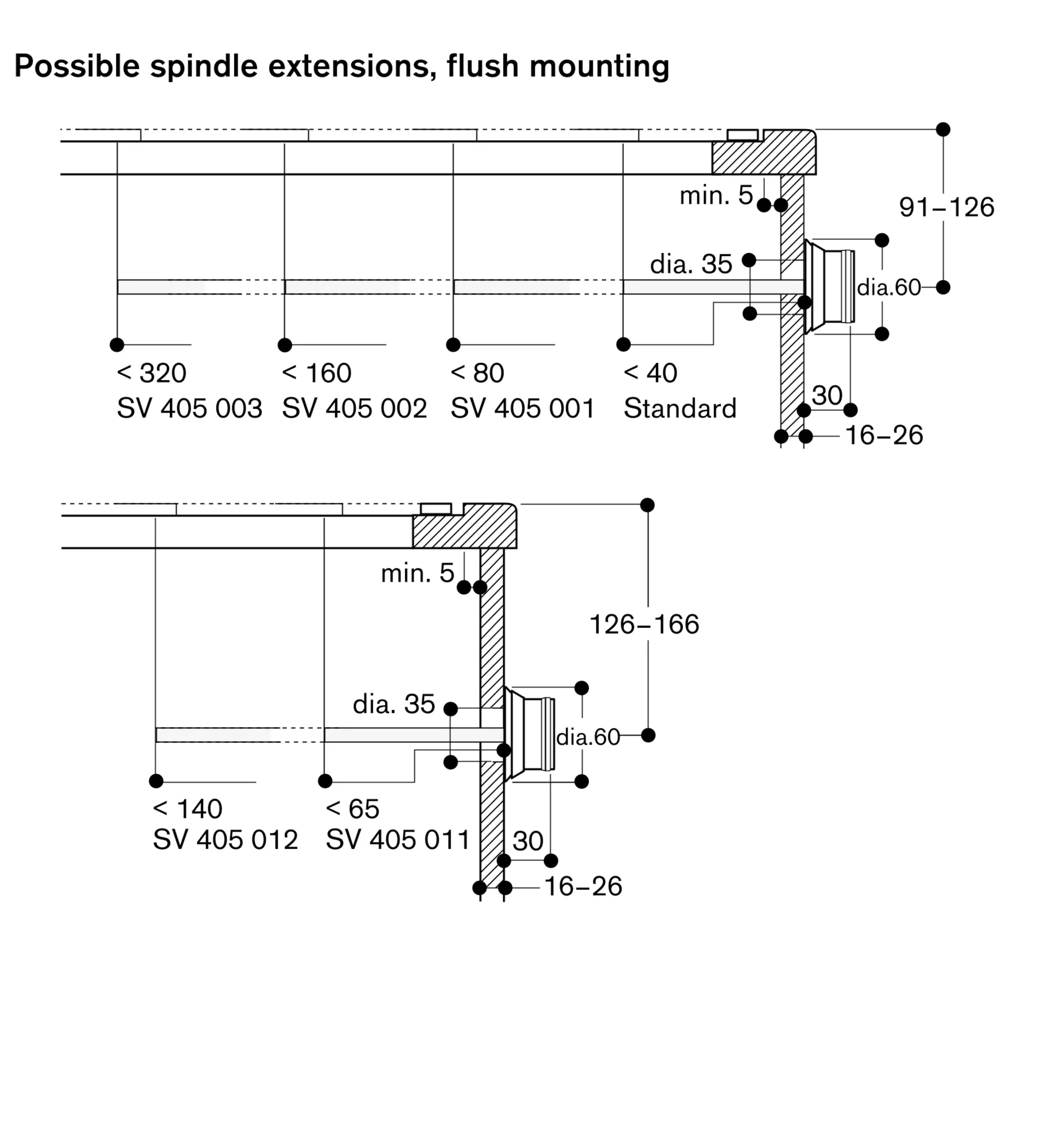
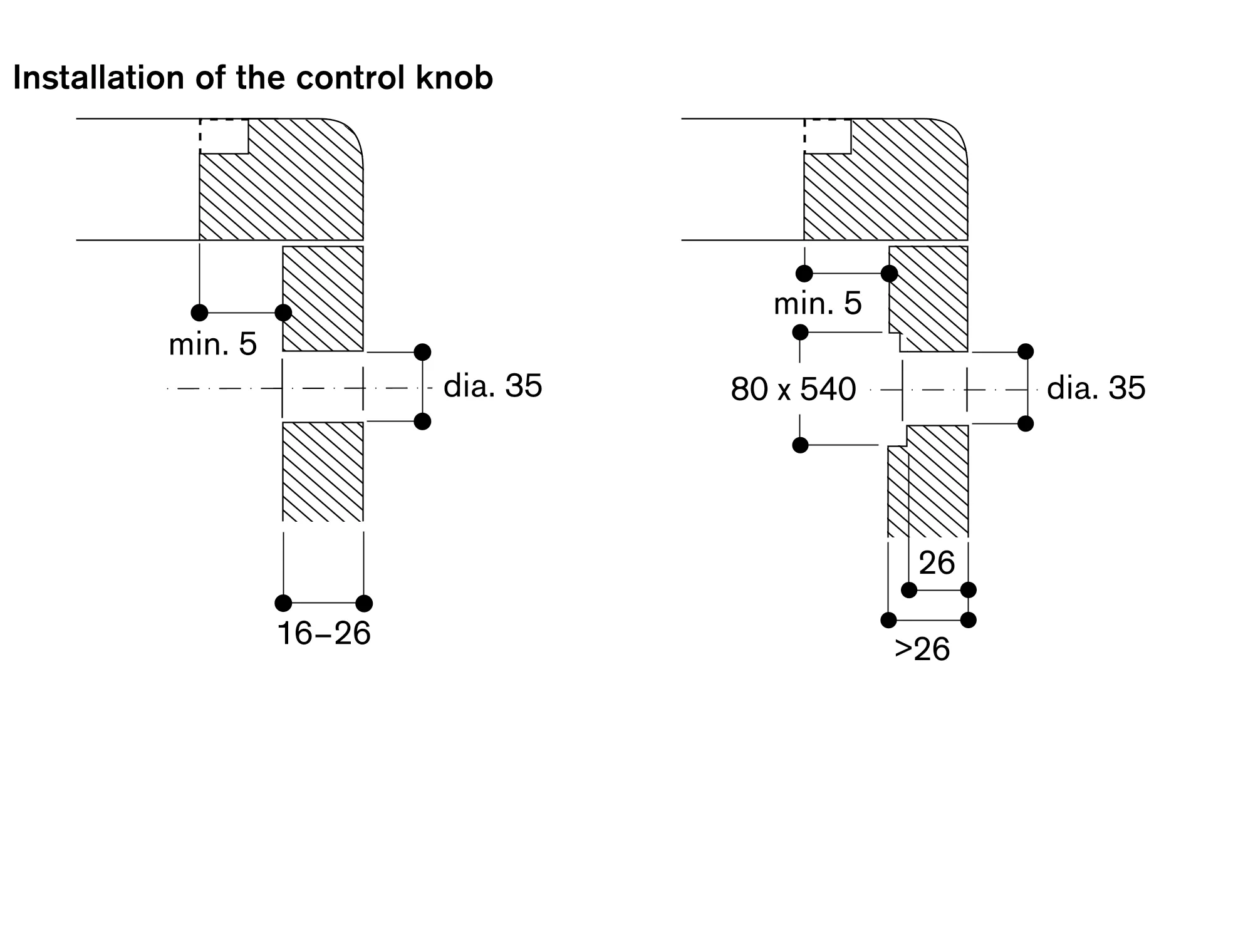
Control knobs to be integrated in the bottom cabinet at drawer level.
Panel thickness 16 – 26 mm.
The drawing "Installation of the control knob" must be observed if the panel is more than 26 mm thick (there must be a recess at the rear).
Special nozzles can be ordered as spare parts.
Plan for an electrical connection (the appliance is not operable without power supply).
Air intake from above.
No intermediate shelf required.
Rear panel and wall trims must be heat-resistant and consist of a non-flammable material.
A minimum lateral clearance of at least 300 mm from adjacent heat-sensitive furniture or contact surfaces must be observed or thermal insulation fitted.
Installation in a 90 cm wide lower cabinet is required.
The combination with VL 414 is not recommended, since the air extraction from the centre burner cannot be guaranteed due to the distance.
With a total connected load of more than 12 kW local regulations concerning room ventilation, room size and combination of extraction or recirculation hoods must be observed. Minimum clearance between gas cooktop(s) with more than 12 kW and ventilation hood 70 cm.
Appliance can be snapped into the worktop from above.
Appliance weight: approx. 33.
Total connected load gas 18.0 KW.
Total connected load electric 15.0 W.
Connecting cable 1.4 m with plug.